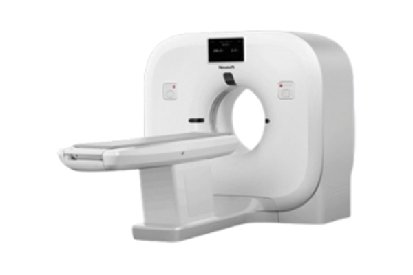
CT
CARE60 is a cutting-edge collection of dose management technology adopted directly from 512- slice CT platform. ClearView Advanced Iterative Reconstruction Algorithm facilitates noise reduction at 60kV to actualize uncompromised low dose imaging.
With performance-enhancing innovations from start to finish, NeuViz ACE integrated market-leading high definition solutions into its imaging chain to set new standards of image quality and clinical excellence for cost-effective CT scanners.
NeuViz ACE maximizes data collection and utilization, by leading-edge advancement Micro120 (accompanying with micro-star detector), NeuViz ACE can reconstruct up to 120 slices (min. 0.1 mm overlapping) for all scans independent of pitch. The increased slices in z-axis drastically suppresses spiral artifacts while vastly increases spatial resolution, thereby enabling to reveal micro lesions, tiny structures and contour delineation for outstanding clinical results.
With the assistance of Spectral Imaging, NeuViz ACE allows acquisition of both anatomical and functional information, providing better contrast images, tumor homology analysis, material separation and affirmation of eff-z number, meaning major gains in specificity and diagnostic accuracy.
Hardware Configuration
- Gantry System Aperture: 650 mm; Scan Field: 445 mm(Large), 250 mm(Small); Tilt: digital tilt ± 30°; Rotation Time: 0.71 s, 1.0 s, 1.5 s, 2.0 s, 3.0 s; Focus to Iso-center Distance: 570 mm; Focus to Detector Distance: 1003 mm; Laser Light: 2 internal laser light locallzers and 4 external light locallzers with accuracy within ± 2 mm.
- Data Acquisition System Max. Number of Slices: 16 slices/rotation(acquired slices); 120 slices/rotation(reconstructed slices by Micro120); Number of Detector Rows: 16 rows; Detector Elements: 11264; Number of Projections: 2320 views/rotation; Up to 30% SNR improvement compared to conventional CT detectors; Down to 1us-2us decay time for sub second scan application; Ultra low afterglow; Special design to minimize electronic noise; High geometric efficiency.
- X-Ray Tube & Generator Tube Current Range: 10 mA-320 mA Tube Voltage: 60 kV, 70 kV, 80 kV, 100 kV, 120 kV, 140 kV; Tube Anode Heat Storage Capacity: 3.5 MHU; Cooling Rate: 742 kHU/min(8.75kW); Focal Spot Size: 1.4×1.2 mm(Large), 0.8×0.7 mm(Small); Max. Power: 32 kW; Slip Ring: Low-Voltage.The X-ray tube is designed for high patient throughput at a low running cost. The insulation layer outside the anode target surface preserve tube heat to avoid tube waste during warm-up, while high cooling rate assists in accommodating large volume of patients.
- Patient Table Max.Table Load: 205 kg/330 lbs; Table Feed Speed: 1 mm/s-100 mm/s; Horizontal Movement Range: 0-1570 mm; Vertical Travel Speed: 9-19mm/s; Vertical Travel Range: 480-940 mm.
- Host Computer Systems High-performance Computer: Monitor: 23 inch, 1920 x 1080 resolution; DELL P2319H Host: Dell T3630 CPU: Intel Core i5-8500 Processor (6 Core, 3.0GHz, 9MB Cache, Integrated graphics: HD 630) RAM: 16GB (2 x 8GB, 2666MHz, DDR4, UDIMM) System Disk: 1TB, 3.5 inch SATA3.0 Disk (7,200 rpm) Data Disk: 1TB, 3.5 inch SATA3.0 Disk (7,200 rpm) Recon: Dell T5820 CPU: Intel Xeon W-2123 Processor (4 Core, 3.6GHz, 5.5MB Cache) RAM: 16GB (2 x 8GB, 2666MHz, DDR4, RDIMM) GPU: GTX 1660Ti System Disk: 500GB, 3.5 inch SATA3.0 Disk (7,200 rpm) Data Disk: 2TB, 3.5 inch SATA3.0 Disk (7,200 rpm) Images Additional Storage: CD-R 700 MB 1,100 images; DVD DICOM Drive 4.7 GB 8,400 images; Write-RW/+RW/-DL/Read. DICOM Viewer: Included on each CD; Automatically started on the viewer's PC.
- System Performance Patient Registration: Direct input of patient information; Pre-registration of patients at any time prior to scan; Emergency mode allows examination without entering patient data before scanning. Transfer patient information from HIS/RIS via DICOM Worklist; Transfer examination information from scanner into HIS/ RIS via MPPS (Modality Performed Procedure Step).Up to 10,000 protocols can be edited, modified, and stored, the doctors can modify and create the protocols freely!
- Scanning Surview Length: 1500 mm; Views: A.P., Lateral, Dual; Real-time surview: Yes. Sequence Acquisition Sequence Acquisition Modes: 16x0.8 mm, 8x0.8 mm, 4x0.8 mm, 2x0.5 mm; Reconstruction Slice Thickness: 0.5 mm, 0.8 mm, 1.0 mm, 1.6 mm, 3.2 mm, 6.4 mm, 12.8 mm; Max. Scan Length: 1570 mm.Spiral Acquisition Spiral Acquisition Modes: 16x0.8 mm, 8x0.8 mm, 4x0.8 mm, 2x0.5 mm; Reconstruction Slice Thickness: 0.8 mm, 1.0 mm, 1.25 mm, 1.5 mm, 2.0 mm, 3.0 mm, 4.0 mm, 5.0 mm, 10.0 mm; Max. Scan Length: 1540 mm; Pitch: 0.3-1.5(continuous).
- Image Reconstruction Real-time Display: real-time image display during spiral acquisition; Recon Field: 50-445 mm; Recon Time: up to 20 images/s with full cone beam reconstruction; Recon Matrix: 512x512, 768x768,1024x1024; HU Scale: 32,768 to +32,767.
- CINE Display Display of image sequences automatic or interactive with mouse control; Max. Image Rate: 30 frames/s.
- Filming Film application is mainly used for image receipt, image viewing and management, layout setting, print preview and print output.
- Image Transfer/Networking Exam can be selected and moved between NeuViz ACE and any imaging system supporting the DICOM 3.0 standard; DICOM Storage (Send/Receive); DICOM Query/Retrieve; DICOM Basic print; DICOM Get Worklist (HIS/RIS); DICOM MPPS; DICOM Storage Commitment; DICOM Viewer on CD.
Software for Application
- .Bolus Tracking Bolus Tracking is an automated injection planning technique that permits the user to monitor actual contrast enhancement and initiate scanning at a predetermined enhancement level. Combine with the SAS option for full automation and efficacy.
- .SAS Spiral Auto Start integrates the injector with the scanner, allowing the technologist to monitor the contrast injection to check for extravasation and to initiate and stop the scan (with the pre-determined delay) while in the scan room.
- MAR+ (Metal Artifact Reduction) Changes the algorithms in the abnormal area with high pixel value by creating the human mode, which removes the highlighted artifacts and returns it to the real tissue structure.
- Real-time MPR Real-time helical reconstruction mode makes it possible to observe the images being scanned in real time. This mode shows any shift in the slice position in real time and allows the operator to check the scan field on the image, contrast study timing, patient body motion, etc. The patient can therefore be released immediately after scanning.
- CCT * CCT is a scanning mode that allows the physician to perform extended, low-dosescans while performing a biopsy. You can control the scan by pressing the footpedal switch in the scanning room. The resulting images display on a remote monitor in the scanning room,providing near-real-time visual feedback during the biopsy.
- .Prism Imaging* Prism Imaging allows back to back axial and helical acquisition of the same anatomy at two different X-ray energies (kVps). To further improve registration accuracy, patient immobilization may be utilized.
- Low Dose Solution 60kV: 60kV offers clinical breakthroughs in low dose scanning with the most advanced image reconstruction algorithm. Lower radiation dose is achieved without sacrificing image quality. 240 Degree Exposure: Controlled by foot pedal, 240 degree exposure prevents direct exposure to operators during interventional or biopsy procedures, thereby decreasing operational risks, and giving more care to medical personnel. Organ Safe: Organs such as eyes, thyroid, thymus, breast, small intestine and gonads are more sensitive to radiation. Sensitive organs are usually covered with lead apron. However, when sensitive organs are included in the scanning range, Organ-Safe function can reduce radiation dose to sensitive areas with unaffected image quality. Pediatric Protocols: Children are 10 times more sensitive to radiation effects than adults. The oncogenic effect of radiation may have a long latent period (up to decades). Dose is relatively higher for a child's smaller crosssection compared to that of an adult. Age and weight-based infant and pediatric protocols to deliver the best clinical results with minimal dose. New Detector Design: Compared to conventional detectors, modularization detector design with new material increases the signal-to-noise ratio, providing an ideal afterglow. Compact design reduces electron-noise while increases geometric efficiency. The new detector design employs Matric 3D shield to reduce scattering effect, largely eliminating noise and objectively improving image quality. ClearView: Iterative processing in both projection and image space delivering clear image even with low dose. Dose Check: Multiple built-in checks to ensure that scanning dose does not exceed preset values. All preset dose could be re-evaluated before scanning based on estimated CTDI and DLP. 3D Dose Modulation: A low-dose technology based on different patient body sizes, anatomy, tube exposure angles and scanning positions. Automatically recommending the optimal mAs with the lowest possible dose for guaranteed image quality.
Clinical Applications
- 2D Viewer After loading images to 2D Viewer, user can process routine image operations such as windowing, zoom, pan, roll, and enhance.
- MPR/CPR Viewer Used to reformat the tomographic data in view planes orthogonal or inclined to the original slices, or in curved planes for better visualization of organs and tissues, and the relation between them.
- MIP/MinIP/AIP The maximum (minimum and average) intensity projection (MIP, MinIP and AIP) function generates interactive display of ray-traced MIP images from set of CT slices. The user can define volume of interest, tissues, and choose it to be projected or removed.
- VR/3-D/SSD 3D visualization software provides unique simultaneous visualization of vasculature, soft tissue and bone. Support viewing through and beyond surrounding structures.
- Virtual Endoscopy With the help of contrast agent or air, the virtual endoscope can display the normal anatomical structure and abnormal pathological changes in the cavity of organs such as large blood vessels, trachea, colon and other organs in a roaming manner. It is safe to operate and distinguish.
- Vessel Analysis Vessel Analysis (VA) offers a set of tools for general vascular analysis including bone removal, vessel extraction and measurements, with various review modes, such as MIP or VR.
- Brain Perfusion* Brain perfusion software package conducts examination based on directly acquired dynamic CT images after injecting contrast agents. It evaluates the physiological function of organs of the head by analyzing perfusion images, thus completing diagnosis.
- Body Perfusion* Body perfusion software package conducts examination based on directly acquired dynamic CT images after injecting contrast agents. It evaluates the physiological function of organs of the body by analyzing perfusion images, thus completing diagnosis
- Lung Nodules Analysis* Lung Nodules Analysis application defines and displays lung lesions using the original series and follow-up series for comparison to determine the growth of the nodules.
- Dental Analysis* Dental Analysis is used to create true-size (life-size) film images of the mandible and the maxilla to assist oral surgeons in planning implantation or prostheses.
- Virtual Colonoscopy* Virtual Colonoscopy enables dynamic virtual 3D colonic lumen viewing for noninvasive visualization and quantitative assessment of colon polyps.
- Lung Density Evaluation* Lung Density Evaluation is an automated application that provides physicians with quantitative lung (volumetric) emphysema measurement and a visual representation of the diffusion of the emphysema.
- Tumor Assessment* Evaluates the tumor characteristics, whether it’s benign or malignant, provides additional information including location, quantity and size as reference for diagnosis, surgery planning, and/or tracking treatment response for prognosis.
- Prism Viewer* Prism Viewer allows users to view images of 101 energy levels with a variety of parameters and visual tools to assist in accurate lesion detection.
- Nerve System DSA* Nerve System DSA is used to remove bone structure in Nerve System scanning. The structure of Nerve system blood vessel can be displayed clearly and intuitively through adaptive registration with or without contrast agent sequence, one-key boneremoving and various display modes including VR, MIP.
- Fat Analysis* The function include abdominal fat analysis, segmentation of subcutaneous fat and intraperitoneal fat and calculation of subcutaneous fat area, abdominal fat area and peripheral area.
- Bone Density Analysis** Bone density is an important indicator of bone mass, which could reflect the degree of osteoporosis and be an important basis for predicting the risk of fracture. Bone Density Analysis application allows measurement fo bone mineral density, providing a powerful tool for the diagnosis of clinical osteoporosis and determination of fracture healing.
- Lung Nodules ROI** Automatic extraction of lung nodules show the 3D shape, volume and the edges of the nodules. The magnified visualization of the 3D structures of the nodules clearly diaplays the neighboring nodules, aswell as the relationship between the nodules, the blood vessels and the pleura. The follow-up function allows closer abservation of the nodule changes to help determine the nature of the nodules.
- ThreeDPrint** The ThreeDPrint is used to import the segmentation results data from an application to the ThreeDPrint application. It uses algorithms to convert the segmentation results data into grid data and then displays it on the interface. The user can perform various operations on the grid data which allows deiting and optimization to obtain a high-quality grid data model. This grid data model is then saved in a file format the 3D printer can recognize and finally be printed out in 3D.
- Bone Measurement** The Bone Measurement software provides femur head segmentation and various bone data measurement functions, allowing you to observe bone growth. It also can send the measurement results to report.
Dimensions & Weight
Gantry Dimensions:1886 mm(L) x 1012 mm(W) x 1795 mm(H); Gantry Weight: 1099kg; Gantry Package: 2100 mm(L) x 1120 mm(W) x 2080 mm(H); Couch Dimensions: 2932 mm(L) x 675 mm(W) x 800 mm(H); Couch Weight: 291 kg; Couch Package: 2570 mm(L) x 970 mm(W) x 1270 mm(H); Console Table: 1400 mm(L) x 800 mm(W) x 743 mm(H);
Power Supply Requirement
Power requirements: Power capacity: 50 KVA; Input voltage: 380/400 VAC; Voltage variation: ±10%; 3-phase imbalance: less than 5%; Frequency: 50/60 Hz ± 1 Hz; Ground resistance: ≤4 Ω (specialized grounding), ≤1 Ω (grounding system).
Environment requirements
Temperature of Scan room : 18℃~ 24℃; Temperature of control room: 18℃~ 28℃; Humidity of Scan room : 30%~60%; Humidity ofControl room: 20%~ 80%; Temperature of Transportation and Storage : -20℃~+ 55℃; Transportation and Storage: 10%~90%(no-condensing); Running Noise: <70dB(A-weighted).
CT Site Planning
Min. Area of Room: Scanning Room: 4200 mm x 3800 mm; Operating Room: 2000 mm x 3800 mm.
Recommended Are of Room: Scanning Room: 6500 mm x 5200 mm; Operating Room: 3000 mm x 5200 mm
Request Quote
If you have any query about this product, feel free to contact us!